

© 2023 TreeCAD


CADPIPE 3D Design
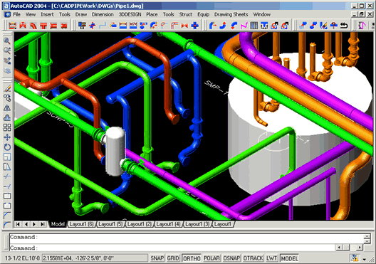
CADPIPE Industrial provides plant designers
with the ultimate mechanical drafting program.
This AutoCAD based program offers User-
Specifications, Automatic Isometric Fabrication
Drawings, Section Views and many other easy to
use time-
User-
CADPIPE Industrial is driven by user-
Automatic Section Views/Spooling
Automatically extract fabrication drawings from your model. A single 3D model can be used to create all scaled plans, sections, elevations, and details with ease.
Automatic Isometric Fabrication Drawings
From your 3D model you can automatically create isometrics, label them, and place a detailed bill of materials report on the drawing. To generate even more detailed ISO drawings, create a Universal Data Exchange (UDE) file of your model and use it to automatically create an isometric in the CADPIPE ISO program.
Collision Warning & Correction
CADPIPE has two collision checking features which examine any area or the entire model for error free designs. Interactive Collision Checking looks for interference with 3D objects as the pipe system is being drawn.
Batch Collision Checking examines your model at the end of the drawing session.
Generate Materials Reports
CADPIPE can automatically generate a complete bill of materials report for one drawing or a global report across a number of drawings. A typical BOM report includes the material specification, schedule, rating, end types, line number, line designation, specification, and many other parameters. You can customize the descriptions or user codes through the specification generator. You can view the complete BOM on your screen, send it to a printer, export it to an SDF file, a comma delimited ASCII file or directly to Microsoft Access for customized sorting of the database information. The ASCII file can be imported into most commercially available databases.
Automatic Pipe Placement
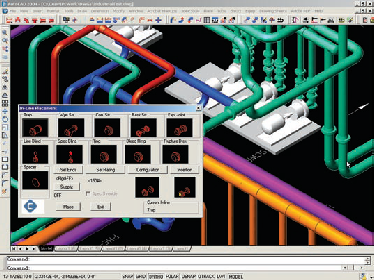
The Automatic Routing Line feature enables you to lay out runs and pipe them instantly. Select any AutoCAD line and it becomes an intelligent CADPIPE routing line, enabling you to automatically place elbows, fittings and pipe.
The Auto-
Annotate Drawings
CADPIPE allows you to annotate your drawing. Simply query CADPIPE's intelligent objects (pipe, fittings, etc), select the appropriate annotation button and drop the annotation text onto the sheet automatically.
Equipment Generator
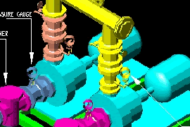
CADPIPE's equipment generator allows you to instantly generate
3D pumps, vessels, and heat exchangers to your own specifications.
Simply select the equipment type and enter the dimensions to quickly
build your customized library.


